
Optical coatings are used to enhance the transmission, reflection, or polarization properties of an optical component. For example, about 4% of incident light will be reflected at each surface of an uncoated glass component.
An anti-reflection coating could be applied to reduce the reflection at each surface to less than 0.1% and a highly reflective dielectric coating could also be applied to increase reflectivity to more than 99.99%. An optical coating is composed of a combination of thin layers of materials such as oxides, metals, or rare earth materials.
The performance of an optical coating is dependent on the number of layers, their thickness, and the refractive index difference between them.
This application note discusses optical coating theory, different types of common coatings, and coating manufacturing methods.
Thin film optical coatings are typically created by depositing dielectric and metallic materials, such as tantalum pentoxide (Ta2O5), aluminium oxide (Al2O3), or hafnium oxide (HfO2), in alternating thin layers.
In order to maximize or minimize interference, they are typically λ/4 optical thickness (QWOT) or λ/2 optical thickness (HWOT) of the wavelength of the light used in the application.
These thin film layers alternate between high index of refraction and low index of refraction, thereby inducing the interference effects needed (Figure 1).

Figure 1:
In a three-layer broadband anti-reflection (BBAR) coating, the correct choice of λ/4 and λ/2 thicknesses of coatings results in a high transmission and low reflection loss.
Optical coatings are designed to enhance the performance of an optical component for a specific angle of incidence and polarization of light such as s-polarization, p-polarization, or random polarization.
Using the coating at a different angle of incidence or polarization than what it is designed for will result in a significant degradation in performance. Sufficiently large deviations in incidence angle and polarization can result in a complete loss of coating function.
Optical Coating Theory
The Fresnel equations of refraction and reflection must be understood in order to comprehend optical coatings. Refraction is the change in direction of a wave’s propagation as it passes from one optical medium to another and is governed by Snell’s law of refraction:
(1)n1sinθ1=n2sinθ2n1sinθ1=n2sinθ2n1 is the index of refraction of the incident medium, θ1 is the angle of the incident ray, n2 is the index of the refracted/reflected medium, and θ2 is the angle of the refracted/reflected ray (Figure 2).

Figure 2: Light moving from a low index medium to a high index medium, resulting in the light refracting towards the interface normal.
The angle of a ray anywhere in a multilayer thin film coating consisting of plane parallel surfaces of different refractive indices can be found using Snell’s law. The internal angle of the ray in the film is independent of the film order or the location of the film in the stack because Snell’s law applies at each interface (Figure 3):
(2)n1sinθ1=n2sinθ2=n3sinθ3=n4sinθ4n1sinθ1=n2sinθ2=n3sinθ3=n4sinθ4

Figure 3: The refracted angle of a ray at any layer in a multilayer thin film coating consisting of plane parallel surfaces is independent of the layer order and can be found using Snell’s law.
The exiting ray in Figure 3 will be parallel to the incident ray because n1 = n4. Optical coatings on curved surfaces are not truly plane parallel structures due to the curvature of the optic. However, this approximation is still valid due to the thinness of the coatings.1
The law of reflection states that the angle of a reflected ray, with respect to the surface normal, is of equal magnitude to the angle of incidence, but of opposite direction with respect to the surface normal.
(3)θ1=−θ2θ1=−θ2
If the angle of incidence of a ray passing from one medium to another with a lower refractive index is larger than the critical angle of a material (θC) defined by the ratio of the two refractive indices, total internal reflection will occur and the ray will be completely reflected (Figure 4). The angle of refraction equals 90° when the incident angle is exactly equal to the critical angle.2
(4)θC=n2n1θC=n2n1

Figure 4: Demonstration of total internal reflection (TIR) where the incidence angle is larger than Θc
The amplitude coefficients for transmission and reflection at the interface between two optical media are governed by the Fresnel equations for transmission and reflection:3
(5)ts=2n1cosθ1n1cosθ1+n2cosθ2ts=2n1cosθ1n1cosθ1+n2cosθ2
(6)rs=n1cosθ1−n2cosθ2n1cosθ1+n2cosθ2rs=n1cosθ1−n2cosθ2n1cosθ1+n2cosθ2
(7)tp=2n1cosθ1n1cosθ2+n2cosθ1tp=2n1cosθ1n1cosθ2+n2cosθ1
(8)rp=n1cosθ2−n2cosθ1n1cosθ2+n2cosθ1rp=n1cosθ2−n2cosθ1n1cosθ2+n2cosθ1
Where ts and tp are the amplitude transmission coefficients for s- and p-polarization, rs and rp are the amplitude reflection coefficients for s- and p-polarization, n1 and n2 are the refractive indices of the two optical media, θ1 is the incident angle, and θ2 is the transmitted or reflected angle. At normal incidence, θ1 and θ2 are 0 making all cosine terms 1 and the amplitude coefficients the same for both polarization states. This makes intuitive sense as there is no distinction between the s- and p-polarization states at normal incidence.
Reflection occurs when light strikes electrons on the surface of the material it is entering. The electrons absorb and re-emit the light with some energy loss. Shiny, highly reflective mirrored materials have more electrons with free mobility, leading to maximum reflection and minimal transmission.
Coating Technologies
There are several physical vapour deposition technologies commonly used to apply optical coatings including ion-assisted electron-beam evaporative deposition, ion beam sputtering, advanced plasma deposition, and plasma-assisted reactive magnetron sputtering (Table 1). No single coating technology is the ideal choice for every application, as each technology has unique strengths that make it optimal for some specific and overlapping use cases.
| E-Beam IAD | APS | PARMS | IBS | |
| Spectral Performance | Stable | Stable | Stable | Very Stable |
| Coating Stress | Low-Medium | Medium-High | Medium-High | High |
| Repeatability | Med-High | High | High | Very High |
| Layer Density | Med-High | High | High | Very High |
| Layer Smoothness | Med-High | High | High | Very High |
| Process Time | Fast | Intermediate | Slow-Intermediate | Slow |
| UV Capability | High | Medium-High | Medium | Low-Medium |
| Substrate Geometry | Very Versatile | Versatile | Limited | Limited |
| Relative Price | $ | $$ | $$ | $$$ |
Table 1: The key parameters of common coating technologies show that the ideal coating technology for a given situation is highly application dependent (E-Beam IAD: ion-assisted electron-beam evaporative deposition, IBS: ion beam sputtering, APS: advanced plasma deposition, and PARMS: plasma assisted reactive magnetron sputtering)
Ion-Assisted Electron-Beam Evaporative Deposition
Ion-assisted electron-beam (IAD e-beam) evaporative deposition is a coating technique in which an electron gun bombards and vaporizes source materials in a vacuum chamber.
The resulting vapour condenses onto optical surfaces and forms uniform, low-stress layers of specific designed thicknesses. IAD e-beam coatings feature low losses in the ultraviolet (UV) spectrum and high laser-induced damage thresholds (LIDTs) in the near infrared (NIR) spectrum. This technique also offers more flexibility for coating design than other methods, as it can use the widest range of useable materials.
IAD e-beam evaporative deposition machines also produce coatings at a lower cost than other methods and accommodate larger coating chamber sizes. This coating technology is ideal for situations when flexibility and cost are the top priorities over high performance.
Depending on the exact ion source used, this technique can result in coatings with lower densities, limited smoothness and reflectivity, and less repeatable properties. This can make precise layer thickness control more challenging than when using ion beam or magnetron sputtering. For this reason, IAD e-beam evaporative deposition cannot create extremely low or high reflectivity coatings, such as an anti reflection V-coat with 99.95% transmission at 1064nm.
Ion Beam Sputtering
Ion beam sputtering (IBS) is a highly-repeatable coating technology that creates coatings of very high optical quality and stability. During IBS, a high-energy beam of ions bombards a target of the desired coating material, causing target atoms to “sputter” off the target (Figure 5).
The target atoms experience a significant kinetic energy (~10’s to 100’s eV), which causes them to form a dense, hard, and smooth film on the surface of optical components.5 One of the main advantages of IBS is that it allows for precise monitoring and control of parameters including layer growth rate, oxidation level, and energy input, resulting in highly repeatable coatings.
High-speed substrate rotation also contributes to exceptional layer thickness accuracy. This allows IBS to create some of the most demanding optical coatings, including ultra-low loss mirrors with reflectivity values above 99.9%, chirped mirrors for ultrafast laser applications, and filters with very sharp spectral transitions.
The performance of IBS coatings is also less affected by environmental factors, such as temperature and humidity, than that of other coating technologies. However, there are several drawbacks to IBS coatings, including higher stress and loss in the UV spectrum.
Slower growth rates and chamber sizes also lead to a significantly higher relative cost than other coating methods, which limits IBS to certain applications when high performance is required.

Figure 5: IBS is a highly-controllable process which utilizes a high-energy ion gun to sputter material off a target onto rotating substrates, resulting in very accurate and repeatable optical coatings
Advanced Plasma Sputtering
Advanced plasma sputtering (APS) is a modified version of IAD e-beam evaporative deposition that benefits from advanced automated processing capabilities.
APS utilizes a hot cathode DC glow discharge plasma instead of an ion beam to deposit coating material. The plasma fills the entire coating chamber, releasing target ions and depositing them on optical surfaces. APS results in smooth, dense, and hard coatings that offer more stable optical properties than IAD e-beam while keeping IAD e-beam’s high level of versatility.
APS can also deposit coatings in volume at a similar price structure to IAD e-beam evaporative deposition, making it preferable when large volumes of coatings with slightly more demanding performance requirements. However, APS experiences higher stress, has more loss in the UV spectrum, and requires iterative process development which leads to a slightly higher cost compared to IAD e-beam evaporative deposition.
In many aspects, APS, along with magnetron sputtering, can be considered an intermediate solution for many parameters between IAD e-beam evaporative deposition and IBS.
Plasma Assisted Reactive Magnetron Sputtering
Plasma assisted reactive magnetron sputtering (PARMS) is another plasma generation-based coating technology.
A glow discharge plasma is generated like in APS, but a magnetic field “confines” it near the target instead of filling the entire coating chamber. The plasma accelerates positive ions onto the target, ejecting target atoms which deposit onto optical surfaces.
PARMS operates at a relatively low chamber pressure at high efficiency because of the confinement of the plasma. This low pressure reduces setup time and allows for more economical coating of high-volume optics. Thin-film coatings formed by PARMS are hard and dense due to reactive gasses added to improve the stoichiometry of the coatings. PARMS is highly repeatable, but not as highly a repeatability as IBS. However, PARMS has a higher throughput, making it an appealing middle ground between the high price and performance of IBS with more economical coating technologies such as IAD e-beam evaporative deposition.
PARMS is often used to manufacture fluorescence filters because of the technology’s balance of relatively high optical performance and relatively high-volume throughput.
Anti-Reflection (AR) Coatings
ATE offers all transmissive optics with a variety of anti-reflection (AR) coating options that vastly improve the efficiency of the optic by increasing transmission, enhancing contrast, and eliminating ghost images.
Most AR coatings are also very durable, with resistance to both physical and environmental damage. For these reasons, the vast majority of transmissive optics include some form of anti-reflection coating.
When specifying an AR coating to suit your specific application, you must first be fully aware of the full spectral range of your system. While an AR coating can significantly improve the performance of an optical system, using the coating at wavelengths outside the design wavelength range could potentially decrease the performance of the system.
Why Choose an Anti-Reflection Coating?
Due to Fresnel reflection, as light passes from air through an uncoated glass substrate approximately 4% of the light will be reflected at each interface. This results in a total transmission of only 92% of the incident light, which can be extremely detrimental in many applications (Figure 1). Excess reflected light reduces throughput and can lead to laser-induced damage in laser applications.
Anti-reflection (AR) coatings are applied to optical surfaces to increase the throughput of a system and reduce hazards caused by reflections that travel backwards through the system and create ghost images. Back reflections also destabilize laser systems by allowing unwanted light to enter the laser cavity.
AR coatings are especially important for systems containing multiple transmitting optical elements. Many low-light systems incorporate AR coated optics to allow for efficient use of light.

Figure 1: Fresnel reflections occur at every material interface. Part of every reflected ray will experience additional Fresnel reflection each time it reaches an additional interface1
AR coatings are designed so that the relative phase shift between the beam reflected at the upper and lower boundaries of a thin film is 180°.
Destructive interference between the two reflected beams occurs, which cancels out both beams before they exit the surface (Figure 2). The optical thickness of the optical coating must be an odd integer multiple of λ/4, where λ is the design wavelength or wavelength being optimized for peak performance in order to achieve the desired path difference of λ/2 between the reflected beams. When achieved, this it will lead to the cancellation of the beams. The index of refraction of a thin film (nf) needed for complete cancellation of the reflected beams can be found by using the refractive indices of the incident medium (n0) and the substrate (ns).
(1)nf=√n0nsnf=n0ns

Figure 2: The refractive index and thickness of every coating layer is carefully controlled in order to cause destructive interference between every reflected beam.
Anti-reflection V-coats are a type of AR coating designed to increase transmission over a very narrow waveband centred at a specified design wavelength (DWL).
This coating type is called “V-coat” because the curve of the transmission versus wavelength forms a “V,” with a minimum at the DWL. V-coats are ideal for obtaining maximum transmission when using single-frequency, small line width lasers, or narrow full width-half max (FWHM) light sources.1 V-coats typically have a reflectivity of less than 0.25% at the DWL. However, the reflection curve for the coating locally has a nearly parabolic shape and the reflectivity is significantly higher at wavelengths besides the DWL (Figure 3).
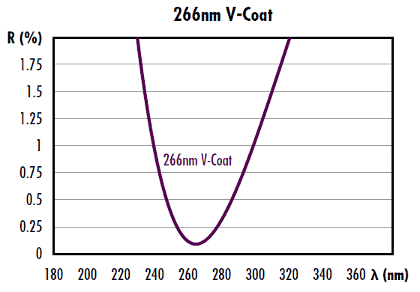
Figure 3: Example of a laser V-coat designed for maximum transmission at 266nm
Table 1 shows the reflectivity and guaranteed laser-induced damage threshold (LIDT) for EO’s standard laser V-coats.
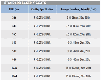
Table 1: Reflectivity specifications and guaranteed laser induced damage thresholds for EO’s standard laser V-coats – custom wavelengths available upon request.
Because reflectivity increases rapidly as the wavelength of the source moves further away from the DWL, optical components with V-coats are meant for use at exactly or very close to the intended DWL of the coating.
An interesting characteristic of V-coats is that the shape of their transmission curves is semi-periodic such that the reflectivity reaches a local minimum at harmonics of the DWL (e.g. λ0/2 or λ0/4) that are not as optimized for reflectivity as at the DWL. V-coats are usually comprised of only two coating layers. Simple V-coats can consist of a single layer with a thickness of a λ/4, but more layers may be required to adjust the bandwidth or if a coating material with an appropriate index of refraction is not available.
Multilayer coatings may also compensate for different angles of incidence, but are more complicated and tend to have larger bandwidths. If the thickness of the V-coat layers are incorrect, the reflectivity of the coating increases and the DWL changes. V-coats from ATE Optics typically achieve minimum reflectivities significantly less than 0.25%, but all standard V-coats have specified reflectivities of <0.25% at the DWL. This allows for small shifts in the DWL from coating tolerances.
Broadband anti-reflection (BBAR) coatings are designed to improve transmission over a much wider waveband. They are commonly used with broad spectrum light sources and lasers with multiple-harmonic generation.
BBAR coatings typically do not achieve reflectivity values quite as low as V-coats, but are more versatile because of their wider transmission band. In addition to being applied to transmissive optical components including lenses and windows, AR coatings are also used on laser crystals and non-linear crystals to minimize reflections, as Fresnel reflections occur where air and the crystal meet.1
Broadband Anti-Reflection (BBAR) Coating Options
ATE Optics offers all lenses with an optional single-layer, dielectric anti-reflection (AR) coating to reduce surface reflections. In addition, custom single-layer, multi-layer, V, and 2V coatings are available for both our off-the-shelf and large volume custom orders. View Custom Optical Lens Coatings for information.
Figure 4: Wavelength selection chart
λ/4 MgF2: The simplest AR coating used is λ/4 MgF2 centred at 550nm (with an index of refraction of 1.38 at 550nm). MgF2 coating is ideal for broadband use though it gives varied results depending upon the glass type involved.
VIS 0° and VIS 45°: VIS 0° (for 0° angle of incidence) and VIS 45° (for 45° angle of incidence) provide optimized transmission for 425 – 675nm, reducing average reflection to 0.4% and 0.75% respectively. VIS 0° AR coating is preferred over MgF2 for visible applications.
VIS-NIR: Our visible/near-infrared broadband anti-reflection coating is specially optimized to yield maximum transmission (>99%) in the near infrared.
Telecom-NIR: Our telecom/near-infrared is a specialized broadband AR coatings for popular telecommunications wavelengths from 1200 – 1600nm.
UV-AR and UV-VIS: Ultraviolet coatings are applied to our UV fused silica lenses and UV fused silica windows to increase their coating performance in the ultraviolet region.
NIR I and NIR II: Our near-infrared I and near-infrared II broadband AR coatings offer exceptional performance in near-infrared wavelengths of common fibre optics, laser diode modules and LED lights.
SWIR: Short wave infrared broadband AR coating for applications from 900 – 1700nm.
Figure 5, Figure 6, and Table 2 show EO’s standard BBAR coating options.

Figure 5: EO’s standard AR coatings for the visible spectrum.
Figure 6: EO’s standard AR coatings for the near infrared (NIR) spectrum cover 400 – 1600nm, but custom coatings can be designed out past 2µm.

Figure 7: EO’s standard AR coatings for the infrared (IR) spectrum.
Table 2: Reflectivity specifications for EO’s standard BBAR coatings
Anti-reflection coatings are available on the following TECHSPEC® Optics
Lenses
Prisms

Windows
Metallic Mirror Coatings
ATE manufactures a wide range of precision parabolic, spherical, and flat mirrors with a number of different substrate materials.
These products are offered in a variety of metallic and dielectric coatings to suit all your application requirements. Metallic mirror coatings are optimized for different regions of the spectrum. ATE Optics® offers a series of metallic coatings for applications using wavelengths ranging from 120nm to beyond 10μm.
Our standard metallic mirror coatings include Protected Aluminium, Enhanced Aluminum, UV Enhanced Aluminum, DUV Enhanced Aluminum, Bare Gold, Protected Gold, and Protected Silver. Protected Aluminum and Enhanced Aluminum are typically used for visible applications. UV and DUV Enhanced Aluminum can be used for UV and visible applications. Bare or Protected Gold offers high reflectance for nearInfrared (NIR) and Infrared wavelengths. Protected Silver provides the highest reflectance between 500 – 800nm and also performs well in near-Infrared and Infrared applications.
Introduction to First Surface and Second Surface Mirrors
All of our mirrors are first surface mirrors, (Figure 1) featuring a high reflectance coating deposited on the front surface of a variety of different types of glass, metal, or semiconductor substrates.
First surface mirrors are recommended for use in precision optics applications. Second surface mirrors (Figure 2) can be manufactured using similar coating technology, but the incident light first passes through a transparent substrate material before it is reflected by the coating.
This geometry helps protect the coating layer from scratches and oxidization but leads to several other important issues that make this type of mirror unsuitable for most precision optics applications:
- Light incident on a second surface mirror is subject to chromatic dispersion from the substrate material.
- Reflection at the substrate leads to ghost images, indicated by the dashed orange line. A second unwanted reflection occurs as the light exits the substrate decreasing the net reflectance of the mirror. Additional stray ghost reflections may also be seen as the light bounces between the coated and non-coated surfaces of the substrate.
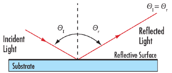

Figure 2: Reflection from a Second Surface Mirror showing the ghost reflection and refraction in the mirror substrate.
What is an Enhanced or Protected Metal Coating?
Metal coatings are typically very delicate without a protective coating and require extra care during handling and cleaning. The surface of an unprotected metal coating should never be touched or cleaned with anything but clean, dry air. A dielectric overcoat on a metallic mirror allows for improved handling of the component, increases the durability of the metal coating and provides protection from oxidation with little impact to the performance of the metal coating.
The dielectric layer(s) can also be designed to enhance the reflectance of the metal coating in specific spectral regions. Isopropyl alcohol or acetone can be used to clean our protected metal coated mirrors. A mirror coating selection guide is given in Figure 3 below and summary of key parameters is given on Table 1.
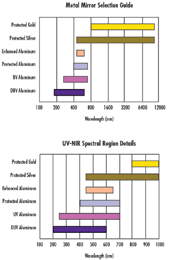
Figure 3: Metallic Mirror Coating Reflectance Curves – Theoretical reflectance rises gradually through 10μm.
Protected Aluminium
Standard protected aluminium is our most popular mirror coating for applications in the visible and near infrared. A λ/2 coating of Silicon Monoxide (SiO) is typically used as an overcoat to protect the delicate aluminium.
This treatment provides an abrasion-resistant surface while maintaining the performance of aluminium mirror.
Enhanced Aluminium
In an Enhanced Aluminium coating, a multi-layer film of dielectrics on top of aluminium is used to increase the reflectance in the visible or ultraviolet regions.
This coating is ideal for applications requiring increased reflectance from 400 – 650nm while the UV and DUV Enhanced Aluminium coatings yield increased reflectance from 120 – 400nm range.
The multi-layer film also provides the improved handling characteristics of the protected aluminium coating.
Protected Silver
Silver offers high reflectance in the visible and infrared spectral regions, making it an excellent choice for broadband applications that span multiple spectral regions.
A protective coating reduces silver’s tendency to tarnish but the coating still performs best in low humidity environments.
Bare and Protected Gold
Gold coatings are effective for applications requiring high reflectance in the NIR and IR regions. Since a durable coating is necessary in many applications, we offer gold with a protective overcoat.
The performance of gold (96% reflectivity from 750 – 1500nm) is maintained, but the optic has a more durable finish.
| Table 1: Metallic Mirror Coating Summary | |||
| Name | Wavelength Range | Reflection Specifications | Typical Energy Density Limit |
| VUV Enhanced Aluminium | 120-125nm | Ravg >78% | |
| 120-700nm | Ravg >88% | ||
| DUV Enhanced Aluminium | 190-195nm | Ravg >88% | |
| 190-600nm | Ravg >85% | ||
| UV Enhanced Aluminium | 250-450nm | Ravg >89% | 0.5 J/cm2 @ 355nm, 10ns |
| 250-700nm | Ravg >85% | ||
| Protected Aluminium | 400-700nm | Ravg >85% | 0.3 J/cm2 @ 532nm & 1064nm, 10ns |
| 400-2000nm | Ravg >90% | ||
| Enhanced Aluminium | 450-650nm | Ravg >95% | 0.2 J/cm2 @ 532nm, 10ns |
| Protected Silver | 450-2000nm | Ravg >98% | 0.5 J/cm2 @ 532nm & 1064nm, 10ns |
| 2000-10000nm | Ravg >98% | ||
| Ultrafast Enhanced Silver | 600-1000nm | Ravg >96% | 0.3 J/cm2 @ 532nm & 1064nm, 10ns |
| Protected Gold | 700-2000nm | Ravg >96% | 0.8 J/cm2 @ 1064nmnm, 10ns |
| 2000-10000nm | Ravg >96% | ||
| Bare Gold | 700-800nm | Ravg >94% | |
| 800-20000nm | Ravg >97% | ||
| 2000-12000nm | Ravg >98% | ||

Figure 4: Typical Reflectance Curves for Metallic Mirror.
Custom Mirror Coatings Available
ATE Optics® is a leading designer and manufacturer of laser coatings for mirrors, beam splitters, windows, and other optical components.
We work with a number of testing laboratories to independently qualify and certify our coatings for resistance to laser damage. All specified damage threshold values have been obtained by testing multiple coating runs to ensure an accurate result.
The values specified are conservative, with typical data showing that our mirrors are able to withstand 2-3 times the specified threshold.
We are able to design and manufacture coatings for single or multiple laser lines, as well as for broadband tunable laser sources. Coatings designs are also available for partial reflectors, output couplers, and etalons, and for any angle of incidence or polarization state.
Our world class manufacturing facilities are able to produce substrates with surface accuracies of < λ/20, surface qualities of 10-5, parallelism of <0.5 arcseconds, and surface roughness of <5 Angstroms in any glass and most crystalline substrates. We will also coat customer-supplied substrates for prototype or production volumes. For high-power applications, coating designers choose materials with intrinsically low absorption at the relevant wavelengths. But the customer also needs to be aware that the choice of coating materials for high-power applications is limited.
The system-designer does well to design for optics with the appropriate damage thresholds from the beginning of the optical design process.
Coatings for use with high-power ultraviolet (UV) lasers are made of different materials from those for use in the visible and near-infrared (IR).
The core structure of high-reflection coatings is typically a repeating stack of high- and low-index layers, each a quarter-wavelength thick. The design of the coating can significantly alter the damage threshold. Simply adding a half-wave of low-index material (normally silicon dioxide) as the final layer can result in measurably higher damage thresholds. Silicon dioxide (SiO2) is the generally accepted and ubiquitous choice for low-index layers, and dielectric metal oxides in general are preferred materials for UV, visible, and near-IR laser applications.
Choosing a material for high-index layers is not as straightforward: oxides of titanium, tantalum, zirconium, hafnium, scandium, and niobium are all popular high-index materials.
BBHR and NBHR (Notch Filter)
- Visible Broadband: Ravg >98%, 425-675nm, 0-45° AOI
- Notch Filter: R >90% at Center Wavelength (CWL), FWHM < 0.12 CWL, Tavg >90% for Out of Band Wavelengths
- Custom Coatings Available for Wavelengths between 300-1800nm (BBHR) and 350-850nm (Notch)

Figure 5: Broadband and Narrow Band High Reflectors
Single and Dual Laser Line Reflector
- Maximum Reflectance at 1 or 2 Customer Selected Wavelengths from 190-3000nm (Single Line) or 350-1700nm (Dual Line)
- Single Line: R >99.5%, at Design Wavelength
- Dual Line: R >98.5%, at Both Wavelengths of Interest

Figure 6: Dual Laser Line Reflector
Laser Line Beam splitter
- Partial Reflectance from 5%R to 95%R, per Customer Requirement
- Reflectance Specification: R% = ±2%; Typical: R% = ±1%
- 45°, Random and Non-polarizing Versions
- Design Wavelengths from 250-3000nm
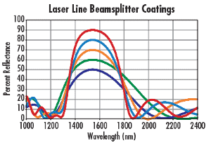
Figure 7: Laser Line Beam splitter Coatings
Capabilities
ATE Optics® produces dozens of stock anti-reflection (AR) and metallic mirror coatings and an even wider range of custom optical coatings in our internal coating facilities.
If our standard coating options will not work for your application, we will work with you to design a custom coating.
- Filters – Fluorescence, Dichroic, Narrow Bandpass, Multi-Bandpass, Notch, Edge (SWP and LWP)
- Anti-Reflection – Single Layer, High Efficiency Multi-Layer (Broadband), Laser V, Double Laser V
- Beam splitters – Polarizing, Non-Polarizing
- High Laser Damage Threshold – Anti-Reflection, High Reflection
- ITO Conductive
- Mirrors – Protected and Enhanced Aluminium, Silver, and Gold, “Hot” and “Cold” Dielectric, Multi-Layer Dielectrics
- Specialized Designs – Build to Print, Custom Design and Development for UV, Visible, Infrared (NIR, MWIR, SWIR, LWIR)
| Shortpass Filter Cut-Off Wavelength | 400 – 1600nm |
| Longpass Filter Cut-On Wavelength | 240 – 7300nm |
| Bandpass Filter CWL, OD, and Bandwidth | 193 – 10,600nm, >OD 7, 1nm – Broadband |
| Notch Filter CWL | 355 – 1064nm |
| Reflective ND Filter OD | OD 0.1 – OD 3 |
| Filter Center Wavelength (CWL) Tolerance | ±1nm |
| Filter Edge Tolerance | <1% Deviation, <0.2% Special Cases |
| Beam splitter (BS) Wavelength Range | 240 – 20,000nm |
| BS Polarization Extinction Ratio (S:P) | 10,000:1 |
| Laser-Induced Damage Threshold (LIDT) | >40 J/cm2 @ 1064nm @ 20ns @ 20Hz Pulses, Measured |
| Durability | MIL-PRF-13830B APP C, PARA C.3.8.4, PARA C.3.8.5, MIL-C-48497A |
*Measured in the UV-visible range